Speech-on-Light for Communication
C Morgan The Radio Constructor, January, 1964.
The need for a simple but efficient system of communication recently arose between two friends. Connection by way of wires was out of the question, and the writer was approached to see whether he could offer any solution to the problem. After some thought he recalled a system of communication that had been used many years ago to provide contact between an aircraft and the ground. This method was known as speech-on-light, and it had considerable success, as long as the aircraft was visible from the ground, at a range of about half a mile or less. Outside that range the system became un-usable.
The basic method of operating a speech-on-light link is to modulate a steady light source with an audio frequency. The fluctuations in light are then converted to AF voltages by a distant photo-cell, applied to an amplifier, and reproduced as audio once again.
A Practical System
The writer decided to see whether this system could be put into use with simple components and equipment, and he found that results were far better than had been anticipated. Due to the nature of the components employed, particularly at the transmitting end, there was a loss of the higher audio frequencies but, whilst this prevented the transmission of music without considerable distortion, speech could be received with perfectly adequate clarity. The system that was finally devised worked satisfactorily over a distance of 100 feet.
The transmitter consists of an amplifier coupled, by way of an audio transformer, to a small filament bulb. Also connected into the bulb circuit is a battery that causes the bulb to be partly illuminated. The audio from the transformer then varies the intensity of light from the bulb and, in consequence, modulates it. See Fig. 1.
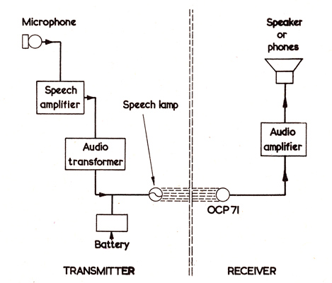
Fig. 1. The Basic speech-on-light communications system.
At the receiver, an OCP71 photo-transistor picks up the modulated light beam and offers an audio output which is fed to an audio amplifier. The output from the latter then feeds a speaker or a pair of phones.
In order to obtain a useful range it is desirable to fit a focusing lens or mirror to both the transmitting lamp and receiving phototransistor.
In the writers case, the amplifier employed at the transmitting end consisted of the triode and pentode audio stages of an AC mains radio fitted with pick-up sockets. The model used had a double-wound mains transformer, with the result that all additional wiring was isolated from the mains supply with a consequent reduction in the risk of shock. The output transformer in the receiver was identified, and the connections to the secondary disconnected from the speaker. A 3 Volt battery and a 2.5 Volt 0.3 Amp torch bulb were then connected in series with the secondary as shown in Fig. 2.
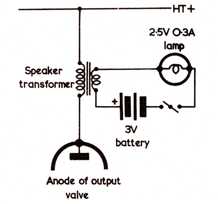
Fig. 2. Connecting the transmitting lamp and battery to the output stage of an AC mains receiver. The receiver speaker is disconnected.
When these connections are made the bulb will, of course, become illuminated. The next process consists of connecting an aerial to the receiver, turning the volume to minimum and tuning in to a station. No sound will, of course, be heard because the speaker is disconnected, but if the volume control is turned up slightly it will be noted that the light from the bulb commences to fluctuate in sympathy with the signal being received. The volume control should not be turned up too high because excessive signal level from the output transformer may cause the bulb to burn out. The volume control should, for similar reasons, be set to minimum when changing from one waveband to another.
After this, a suitable microphone can be connected to the pick-up terminals of the receiver. The writer initially employed an ex-GPO carbon microphone, complete with step-up transformer and energising battery, and this offered more than adequate output. Later, a small moving coil speaker was used instead of the carbon microphone (but still employing the step-up transformer) and, whilst the available output was reduced, the quality of the modulation was noticeably improved.
After the microphone has been connected into circuit, operation may be checked by observing the bulb whilst speaking into the microphone. If there is a fluctuation in the light from the bulb then operation is satisfactory. The receiver volume control will need to be set up for best conditions when the microphone is in use, and it should be remembered that excessive audio at the receiver output transformer can still cause the bulb to burn out.
The Receiver
At the receiving end, all that is required is an OCP71 with associated components, and another audio amplifier. The writer employed a tape recorder amplifier, but it is probable that a two valve amplifier, as used at the transmitter, should prove adequate. Alternatively a small transistor amplifier could be used. (The type of amplifier in an installation of this nature is a matter for experiment. However, unless there is a close coupling via the optical path between the transmitting lamp and the OCP71, it would appear that an amplifier with somewhat greater gain than that offered by the audio stages of a valve radio would be needed. - Ed.)
The OCP71 is connected up in the circuit shown in Fig. 3. In this diagram the inductor L consists of an audio choke. A smoothing choke as employed in a power pack is quite satisfactory here, but a small physical size is desirable in order to reduce the bulk and weight of the OCP71 unit. Fortunately, the limited audio frequencies over which the communications system is required to work do not call for a critical value of inductance in this component.
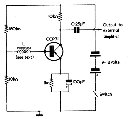
Fig. 3. The circuit in which the OCP71 is employed.
Mounting the Lamp and Photo-transistor
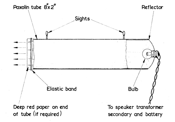
Fig. 4. The transmitting bulb, reflector and housing.
Both the lamp and the photo-transistor can be mounted in similar housings. The lamp housing is shown in Fig. 4 and, as may be seen, this comprises a Paxolin tube fitted at one end with the bulb and its reflector. Two small sights fitted to the outside of the tube assist in aligning the lamp on to the OCP71. An interesting point is that, since the OCP71 is sensitive to infra-red radiation, performance is hardly affected if a red filter is fitted in front of the lamp. The writer found that he could, indeed, obtain satisfactory results by simply employing red paper as a filter. The result is that communication is still obtained, even though the beam of light becomes virtually invisible.
The receiver housing is shown in. Fig. 5, and this is very similar to that used by the transmitting lamp. The phototransistor is mounted in a horizontal position with its base away from the reflector. This ensures that all of its light-sensitive area is illuminated by the light from the transmitter. The reflector employed at the receiver is a glass type and that used by the writer had measurements of 5 cm x 5 cm (ie. diameter and focus). Suitable reflectors are available through some photographic dealers. It is important to note that the OCP71 housing should never be pointed directly at the sun, as the intense light then focused on the cell may ruin it.
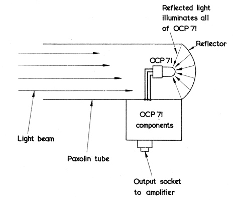
Fig. 5. The OCP71 receiving assembly.
Note. Reference to the Mullard data-sheet on the OCP71 indicates that the device should be mounted perpendicular to the incident light with the most sensitive face being that where the writing is placed - G8LSD.
|