Light-Beam Transmitter-Receiver
J Emmett The Radio Constructor, April, 1963.
Speech and music may be transmitted over a beam of light without interconnecting wire or a radio frequency link. ln this article, our contributor describes a particularly successful light-beam transmitter-receiver which he has designed and built himself.
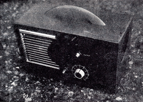
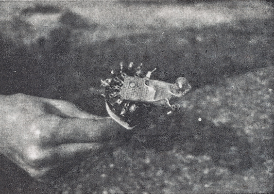
The complete Transmitter-receiver in its cabinet.
Transmission of audio frequencies via a beam of light has been, for some time, the subject of experiments by the writer. With the advent of the phototransistor suitable transmitters and receivers become a feasible proposition, and the writer has had his greatest success with the transmitter-receiver described in this article. The good results obtained have been partially due to the fact that both the transmitting bulb and the receiving phototransistor are fitted into a lens system which provides a closely aligned beam. Despite the fact that a bulb rated only at 5.5 Volts and 0.3 Amps is employed, reliable communication has been obtained at distances in excess of 400 yards.
The transmitter-receiver incorporates a standard transistor amplifier which operates both whilst transmitting and receiving. When transmitting, a microphone is coupled to the input terminals of this amplifier. The audio output of the amplifier then modulates the light from the bulb, the output being superimposed on an adjustable direct current which flows through its filament. When receiving, a phototransistor feeds a transistor pre-amplifier, the output of which is fed to the main amplifier. The latter then drives the loudspeaker.
The Circuit
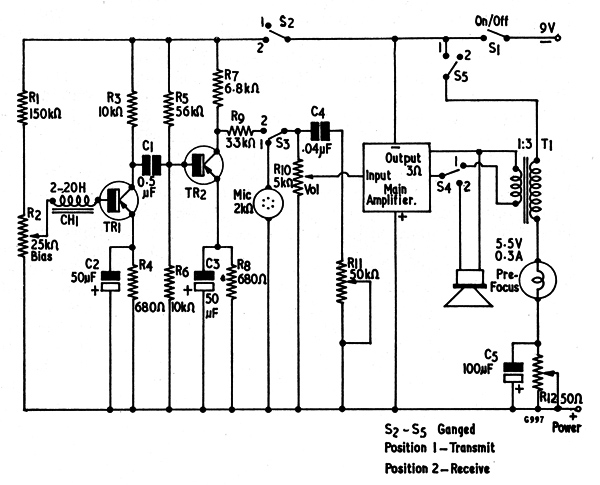
Fig. 1. The circuit of the transmitter-receiver.
The circuit of the transmitter-receiver is given in Fig. 1. In this diagram, switches S2 to S5 are ganged, providing Transmit on Position 1, and Receive on Position 2.
When S2-5 is set to Position 1, the phototransistor and pre-amplifier are switched out of circuit and the microphone is coupled to the volume control R10, the slider of which connects to the input of the main amplifier. This latter employs the line-up, OC71, OC81D and two OC81s, and offers an output of 500mW or more. It was obtained as a kit from Henrys Radio Ltd.
The output of the main amplifier is passed, via S4, to the 1 : 3 transformer T1, the secondary of this transformer being connected in series with the transmitting bulb. The direct current flowing through the bulb is controlled by R12. The amplified microphone signal modulates the bulb current and, in consequence, its illumination.
On Receive (S2-5 in Position 2) the power supply is passed, via S2, to transistors TR1 and TR2. TR1 is a phototransistor, and it is biased by means of potentiometer R2. The choke in the base circuit of TR1 allows DC due to steady light to pass to earth and eradicates frequent readjustments in R2. These were necessary in earlier versions where the choke was omitted. The collector current in TR1 varies according to the modulation of the light by which it is illuminated, and this electrode is coupled to TR2 via C1. TR2 amplifies in normal manner, the signal on its collector being fed, via R9 and the volume control R10, to the main amplifier. The output of the latter connects, via S4, to the loudspeaker.
C4 and R11 form a tone-adjusting circuit, and are not essential to the operation of the transmitter-receiver. If desired, they may be omitted.
Components
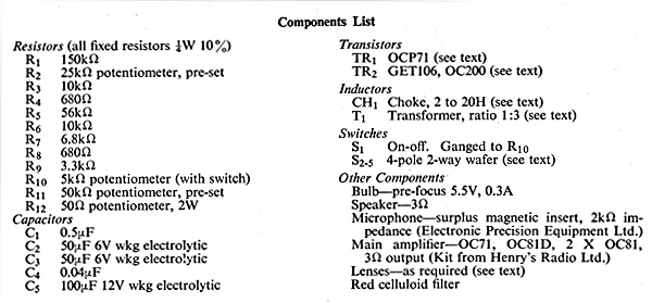
Components List.
There are a number of important points concerning the components used in the transmitter-receiver, and these will now be dealt with.
An OCP71 phototransistor is recommended for the TR1 position, although it should be pointed out that the writer has obtained equivalent results with surplus phototransistors obtained, at much lower cost, from Henrys Radio Ltd. An OC71 with the protective paint scraped away (see Fig. 2) could be used, but it has been found that the more recent versions of the OC71 are opaque and cannot therefore be employed for this application.
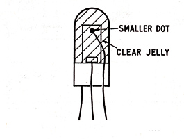
Fig. 2. The light-sensitive section of an OCP71 or older translucent OC71.
The choke in the base circuit of TR1, is experimental. It may be necessary to employ a component of different inductance when finally setting up.
TR2 may be a GET106, or a silicon transistor such as the OC200. An OC71 has been tried in this position, but it caused background hiss to be excessive.
The microphone is a magnetic insert of low- medium impedance (2kΩ), and is a surplus type available from Electronic Precision Equipment Ltd.
Transformer T1 is home-constructed, and is made up in the following manner. Obtain a single-ended speaker transformer capable of handling 5 Watts or more and with the 3Ω secondary winding on the inside. Remove its laminations. Next, remove the primary and determine the number of turns on the 3Ω winding. Wind on three times as many turns with 26 SWG enamelled wire and put a layer of tape on top. Replace the laminations. These should previously have been butt-assembled (ie. all the E laminations on one side and all the I laminations on the other) and they should now be re-fitted in the same manner. If a spacer consisting of thin card or paper was previously interposed between the two sets of laminations this should also be re-fitted. These precautions ensure that the steady direct current which flows through the new winding on Transmit does not saturate the laminations. The previous 3Ω winding now connects to the output of the main amplifier via S4, and the new winding is inserted in the bulb circuit.
If desired, suitable laminations can be bought, in which case winding details are as follows:
- Wind a layer of tape on the core.
- Wind on 30 turns of 26 SWG enamelled wire.
- Add a further layer of tape.
- Wind on 90 turns of 26 SWG enamelled wire.
This method of construction is relatively cheap and simple, but it is desirable to employ a core at least as big as that for an 8 Watt audio transformer.
The transmitting bulb needs to be a type drawing a low current and having a small filament. If the filament is too heavy, all the higher frequency modulation will be cut off. With bulbs such as are used in cycle head-lamps it is possible to see the filament cooling after switching off, and these are of no use for the present application. The writer found that best results Were obtained with a pre-focus torch bulb rated at 5.5 Volts 0.3 Amps.
Resistor R12 regulates the direct current flowing through the bulb. It needs to be rated at 2 Watts or more.
The battery required for the transmitter-receiver has to be capable of providing adequate current for relatively long periods. The PP types are of no use here because of their high internal resistance. Mercury cells or double life pen-cells are cheapest, whilst small nickel-cadmium cells (DEAC units) or accumulators are preferred.
The Focus Unit
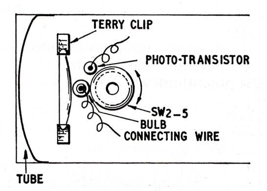
FIG. 3. The lens assembly, showing how the bulb and photo-transistor are fitted to an extension of the Transmit-Receive switch.
The focus unit comprises a Paxolin or cardboard tube some 3in long, in which are fitted one or a pair of enlarger condenser lenses. Two such lenses are shown in Fig. 3, and it is their function to create as narrow a beam as possible. The smaller lens is closer to the bulb, and the prototype employs a 2in type and a 3.5 in type with 0.75in spacing between them. Optical condenser lenses can be obtained from most photographic dealers and a 2in diameter, 4in focus, lens costs around 11s. 6d. However, moulded 2in types are sometimes available much cheaper, at prices around 2s. each. The constructor is advised to check with photographic supply sources in order to obtain suitable lenses at reasonable cost.
The extension of the transmit-receive switch.
A common lens system is employed for both the bulb and the photo-transistor, the latter two components being mounted on an extension of the spindle for S2-5. This arrangement causes the bulb or the phototransistor to be moved to the focal point of the system as applicable, when.ever Transmitor Receive is selected.
A piece of red celluloid (available from most model shops) may be placed over the open end of the tube in order to improve selectivity. This it does by acting as a filter and reducing the light spectrum passed to the phototransistor. The red celluloid clears the buzz given when incident light from mains-operated lamps falls on to the focus tube.
Assembly
The completed transmitter-receiver was fitted in
a light-tight cabinet measuring approximately
9 x 4 x 4in. The speaker and microphone should be
mounted behind a grille. The volume control and
on-off switch, the Transmit-Receive switch, and the
power control (R12) should be fitted on the side of
the cabinet. The bias and tone controls, R2 and
R11, are pre-set, and may be mounted inside. A
larger case, 11 x 4 x 4in would be better, as this
would enable large batteries to be carried.
If desired, the components associated with TR1
and TR2 may be fitted to a printed circuit board.
A suitable design is shown in Fig. 4.
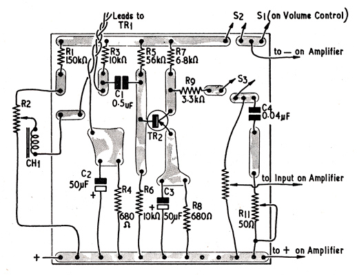
FIG. 4. A suitable printed-circuit layout for the photo-transistor and pre-amplifier stages.
Testing and Setting Up
After the transmitter-receiver has been completed
and the-wiring carefully checked, it requires to be
set up. Before switching on, the controls should
be adjusted in the following manner.
- Bias (R2): one-third to one-half from positive end.
- Tone (R11): half way.
- Power (R12): near positive end.
Select Receive, switch on and turn up the volume. Face the unit (without the red celluloid filter) towards a mains-operated lamp. If there is no 100 Hz buzz, there may be no light falling on the sensitive area of the phototransistor. Other possibilities are that the inductance of the choke in the base circuit of TR1 is too low, or that the bias control needs adjusting.
Switch to Transmit and turn up the power control until the bulb glows. Keep volume at a low level at this stage. This is because it is possible to burn out the bulb by speaking near the microphone if a high volume level has been selected when the bulb is bright. Aim the set at a wall, preferably in the dark, and adjust the position of one lens (or both, if necessary) until a bright image of the filament is seen. This procedure should then be repeated as far away from the wall as possible. A distance of 15ft is suitable.
A torch should next be positioned so that it shines towards the set and is in the centre of the beam from the transmitting bulb. Switch to Receive and position the phototransistor so that its sensitive area is in the focus from the torch beam.
Finally, set the power control to cause approximately 3.7 Volts DC to appear across the bulb. It is not possible to see the modulation of the light from the transmitting bulb, but it should flicker when the microphone is tapped.
Results with the prototype
The prototype has been tested up to a distance greater than 400 yards and there has been hardly any loss. However, aiming is critical, as is to be be expected considering the narrow beam width. Different versions will vary but, by careful adjustment of the lens system, it should always be possible to receive if the transmitting light is visible. If the transmitter-receiver is used during the day, when there is no risk. of 100 Hz buzz from mains-operated lamps, the red celluloid filter can be removed with a consequent increase in power.
In addition to speech, music has also been transmitted. This has been subject to loss of treble, which has been easily corrected by adjustment of the tone control.
|