A Wide-Band Photophone
D Bollen The Radio Constructor, January, March & May, 1967.
Transmission of high quality audio signals over a very wide frequency range is feasible with ordinary fluorescent lighting tubes. In this series, our author introduces the circuit techniques employed at the transmitter and gives a full description of the transmitting lamp reflector and then decribes the receiver circuits.
It should be noted that some of the equipment described in these articles is the subject of a provisional patent application.
The use of a modulated light beam for the transmission of signals has a history as long as that of the telephone. Graham Bell's original Photophone consisted of a thin sheet of silvered glass attached to a mouthpiece, which became alternately concave and convex when sound waves acted upon it, thus affecting the intensity of a reflected light beam. His receiver used a selenium cell as a light sensitive device. An account of his experiments states that 'Speech can be transmitted to a considerable distance by the simple agency of a beam of light', but there was no suggestion that this method would seriously rival the wired telephone. Although the agency is simple, results depend a great deal upon what one means by 'speech' and 'a considerable distance'. Tests carried out by the writer with torch bulb transmitters indicated that muffled tones were sometimes to be heard at distances not further than 100 yards, and the quality of the transmission was poor, even by the standards attainable with wired links in the days of Graham Bell. Perhaps such discouragements are to blame for the meagre interest shown, during the intervening 80 years, in systems employing light as a carrier of modulated signals.
Now, with the radio spectrum fast becoming crowded, together with the development of lasers and other opto-electronic devices, it is possible that light links will be used where radio, wires, and inductive loops are unsuitable. Short range car-to-car communication on the move, talking traffic lights and road signs, ship-to-shore harbour links, private communications networks across streets, and pulse operated remote control systems are a few of the potential uses for a modern Photophone. The fact that interest in such transmissions is very much alive is well demonstrated by the number of interesting articles on the subject that have appeared in The Radio Constructor.
Prototype Experiments
Some time ago the writer experimented with an ordinary fluorescent lamp tube fed from an output valve anode of an audio amplifier as an alternative to the filament bulb with its restricted frequency range. Results were not initially promising. The tube gave a severely distorted signal over a range of a few tens of yards when used with a simple phototransistor receiver. It was realised later that the light from such a tube peaks at the blue end of the visible spectrum, to which a phototransistor is insensitive. A blue sensitive caesium antimony photocell was then purchased, at somewhat more cost than an OCP71, and this worked well when coupled to a high input impedance transistor amplifier at a photocell anode potential of less than 9 Volts. A marked increase in range resulted, and early experiments resulted in speech which was just intelligible at around 200 yards in daylight. Further tests revealed that the distortion of the transmission could be very much reduced if the fluorescent tube was biased with a DC standing current of about 50mA, but the tube then generated a fair amount of noise. This was presumed to be caused by low level self-oscillation due to a negative resistance portion of its slope, and vibration of the discharge striations or rings visible along the length of the tube at the lower audio frequencies. The noise tended to disappear with a high frequency audio signal, and it was found that introduction of a supersonic bias, similar in principle to bias in a tape recorder did much to reduce the noise.
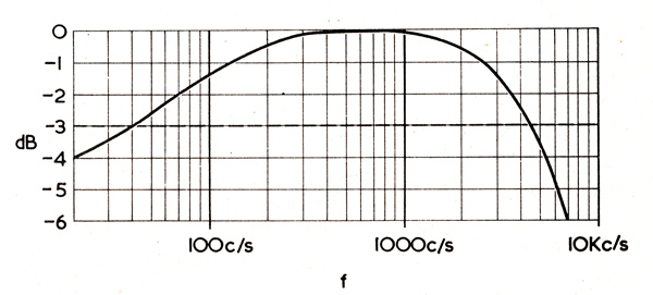
Fig. 1. The overall un-corrected frequency response offered by the Photophone system. By means of suitable compensating circuits, this can be changed to the response shown in Fig. 7.
With the fluorescent tube coupled to a suitable modulation transformer driven by a valve amplifier, the overall un-corrected frequency response was plotted as shown in Fig. 1, and was within 3dB from 40 kHz to 4 kHz. Although this response is much better than that obtained with torch bulbs and a 15 Watt mains bulb, and is adequate for speech communication, it was thought that better results were possible.
A small residual signal as high as 60 kHz, shown on an oscilloscope, prompted attempts to extend the frequency range by compensation, so that music signals could be evaluated. Eventually, with suitable pre-emphasis, a response of 20 Hz to 25 kHz, within 2dB, was obtained. The maximum range at full modulation was also extended to better than 400 yards in bright daylight. Good treble response was well in evidence on music signals, quality was crisp and percussion instruments such as the triangle came through unimpaired.
Tube Unit
With ease of working in view, the tube unit, incorporating DC supply and modulation transformer, was designed to match the 3 or 15Ω output of a standard amplifier, either valve or transistor. The circuit can be modified for portable car battery working by substituting a 15 Watt transistor 50 Hz inverter for the mains transformer supply.
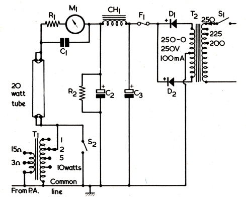
Fig. 2. The power supply for the tube. The modulating signal is applied via transformer T1.
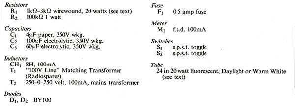
Transmitter components list.
It will be seen, in Fig. 2, that the fluorescent tube is directly modulated by the transformer T1, and that the tube starting heaters are not used. After switching on the equipment the tube will strike on a high level audio peak, attaining full brightness almost immediately. Dropper resistor R1 limits tube current which is monitored by a 100mA meter, to a safe value, and it may be adjusted to suit the fluorescent tube and supply voltage. The correct value of resistor will lie within the range 1kΩ to 3kΩ (start with the high value and reduce this until the desired results are obtained). On no account should the tube ever be connected straight across the 250 Volt DC supply, as this will quickly ruin the tube, and could have spectacular if short-lived results. Capacitor C1 presents a low impedance path to the AC drive which is developed across the secondary winding of the modulation transformer.
T1 is a readily available 100 Volt line transformer wired in reverse. The tag markings - 1 to 10 Watts - do not refer to the power rating of the transformer, but to the sound volume given by a loudspeaker when the transformer is employed normally in a public address system. Although not considered an ideal component for this particular application, the transformer specified for T1 effectively removes the need for a difficult special component. The existing tapping points do provide a correct match to the tube under varying conditions and, despite the high level DC standing current in its windings, this small transformer performs surprisingly well with a good frequency range, and it never even ran warm throughout long-period tests.
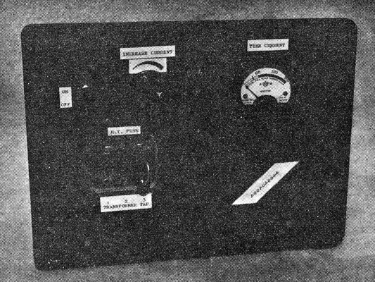
One of several HT supply units made up by the writer.
The original prototype tube consumed 60mA with a 2kΩ dropper resistor for R1, and the voltage across the tube when struck was only 75 Volts. Neglecting losses in the dropper resistor, this means that the tube power is only 4.5 Watts, and yet the light output is roughly equivalent to that given by a pearl 60 Watt mains filament bulb. It is recommended by manufacturers that a low pressure mercury vapour discharge lamp should have its connections reversed periodically when run on a DC supply, to prevent blackening of one end of the tube. As the tube ages, its internal DC resistance will rise, and so will its striking voltage. Old tubes were tried, but they proved reluctant to start and gave a poor light output. Fortunately, because of their mass application, new tubes are relatively inexpensive, and will give a long life.
Construction of the tube supply unit followed standard practice, components being mounted on a small aluminium chassis. C1 was a 4μF paper block capacitor and was situated underneath the chassis, with the mains transformer, rectifiers, electrolytic capacitors, choke and modulation transformer on top. A later version of the unit made provision for switched values of R1 for experimental purposes and to suit cascaded tubes, but this refinement has only a small effect on performance. A terminal block on the back of the chassis is useful for making external connections to the unit. The 100mA meter and switches may be mounted on a front panel, and it is convenient to arrange for sockets to select tappings on the modulation transformer. By closing S2, it is possible to vary the taps without extinguishing the tube.
The tube may be mounted on its own, remote from the amplifier and power supply, but long runs of cable will cause some attenuation of high frequency response, even. at the fairly low impedance at which the tube is fed. If the tube is not visible to the operator, the meter will tell him when the tube is passing current, and will give a useful indication of modulation level.
It is quite possible to use larger fluorescent tubes, or batteries of small tubes, if a power amplifier of sufficient power to modulate them is available. There seems to be no limit on transmitter size. Components will, of course, have to be re-rated to suit the heavier working currents, but the increased output should result in a considerable extension to the range of operation. For modest installations, a smaller 6 Watt tube is available, and its use would enable a very compact layout to be arrived at for instances where long range is not so important. Tubes can also be supplied with a variety of powder coatings, to emit light at different parts of the spectrum, including ultra- violet.
As a guide to readers, the following three tubes may be considered as representative.
- Philips Warm White TLA 20w/35, 20 Watt 24in.
- Atlas ultra violet 20 watt 24in.
- Ekco blue 15 watt 18in.
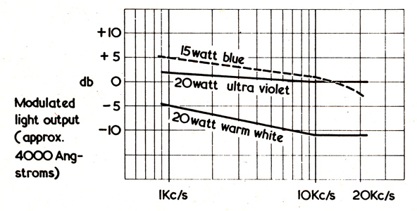
Fig. 3. Un-corrected responses of three fluorescent tubes using a 'flat' amplifier characteristic and constant power input.
Fig. 3 gives a comparison of the performance of these three tubes, from 1 to 20 kHz. The small blue tube is the most efficient (its phosphor output matches closely the response of the photocell), giving the longest range for a given input power, but the high frequency response is poor compared to the other types of tube. The ultra violet is the best all-round tube, with a good output and a very flat response, and the added advantage that its small visible light output makes it inconspicuous in daylight. However, for economy and general working, the much cheaper normal lighting tubes such as the Warm White are satisfactory. There is only a very slight difference between tubes of different manufacture thus far encountered, mainly with regard to noise levels.
Reflectors
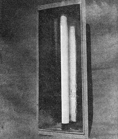
A 20 Watt transmitter tube mounted in its reflector.
When unmounted, the tube will allow 360° transmission of a signal, but a parabolic reflector was constructed to give concentration in one direction and, at the same time, a fairly big light source to make optical receiver alignment simpler. Rather than use large, expensive sheets of polished aluminium, a hardboard and cooking foil method of construction was preferred. In this way, a light source measuring 24 x 9in was obtained, and contacts at several hundred yards were quite simple, without a long search time and erratic reception due to hand shake. In fact, an appreciable deviation of the receiver from true centre can be tolerated without loss of signal, this being better than ±2° of arc.
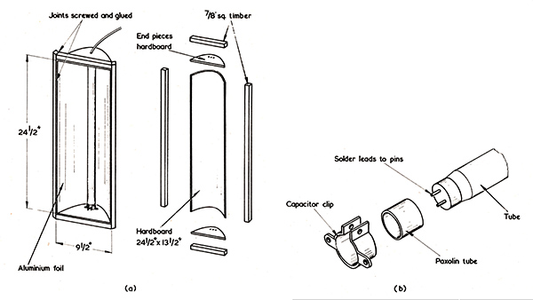
Fig. 4 (a). The assembly of the tube reflector unit (b). Detail showing the method of securing the tube at each end.
Constructional details for the reflector are given in Fig. 4 (a), and the parabolic shaped end pieces may be copied from the drawing of Fig. 5.
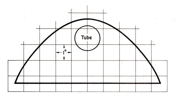
Fig. 5. The end pieces for the reflector. This may be drawn full size on 1 in graph paper to the proportions given here.
The large piece of hardboard forming the body of the reflector is first soaked in a bath of hot water for about an hour to make it pliable. It is then bent roughly to shape and the end pieces are held in place with several windings of string. String is also spirally wound along the body to hold the sides in, and the whole is left to dry. All joints are then screwed and glued and the timber frame is fitted. Details of the tube mountings are given in Fig. 4 (b). Electrolytic capacitor clips were employed to grip Paxolin tubing, into which the fluorescent tube was then fitted. Finally, a layer of bright cooking foil is glued and smoothed on to the reflector body, and the wood frame and hardboard externally painted.
When viewed from a distance, the reflected image of the tube should fill the frame of the reflector. Wires soldered to the tube pins are taken out, top and bottom, to a suitable socket or connector.
Power Amplifier
The approximate impedance of the fluorescent tube is 1,000Ω, this being matched to the output of a 3 or 15Ω valve amplifier by means of the modulation transformer, as described earlier. An amplifier of 15 Watts or more is recommended as this will give an ample reserve of power and prevent amplifier abuse during experiments. The actual power required, including losses, will not be more than 7 Watts at full drive. The amplifier should also be capable of handling a small 45 kHz signal if bias is to be used. Most Hi-Fi amplifiers made today have a response extending well into the supersonic region and are able to handle such a signal at low levels.
Points to watch while setting up the equipment is that the power amplifier is not grossly overloaded, and that it does not become unstable. An oscilloscope is invaluable for modulation tests, but if one is not available an output meter may be connected to the PA output to monitor signal level and check for self-oscillation. A useful pointer to overloading is when the modulation transformer starts to sing loudly: another is the fluorescent tube itself. When over-modulation occurs the tube will flicker. At normal levels of modulation the flicker is scarcely perceptible.
Compensation and Bias
To correct for a fall in frequency response at the extremes of the audio range and beyond, bass and treble boost were included for convenience along with the pre-amplifier and bias circuits in a single unit. There is enough boost to give treble emphasis on transmit and, by introducing a similar amount of treble cut at the receiver, thus improve the signal noise ratio.
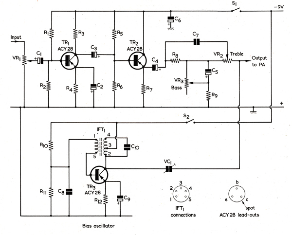
Fig. 6. The circuit of the transmitter pre-amplifier and compensation unit. The internal low-value capacitor between pins 2 and 4 of IFT1 is not shown here.
The pre-amplifier circuit is given in Fig. 6. The signal is amplified by TR1, fed to the emitter follower TR2, and thence into the compensation network composed of R3, R9, C7 and C5. Bass boost is controlled by VR3 and treble boost by VR2.
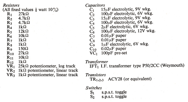
Pre-amplifier and compensation unit components list.
The curve given in Fig. 8 illustrates the type of overall response which can be obtained with suitable low settings of VR2 and VR3. The high frequency response can be extended well into the 50 kHz region for pulse work by substituting a 0.02μF capacitor for C1 in Fig. 2, but this will adversely affect the overall linearity.
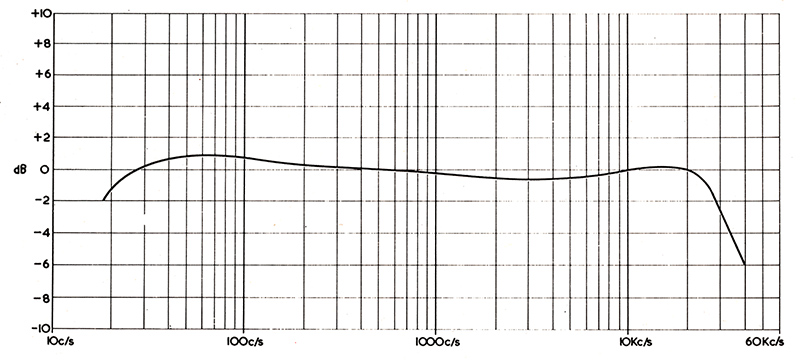
Fig. 7. A typical overall compensated response curve. This is within 2dB from 20 Hz to 25 kHz.
The AC bias oscillator was built around a transistor radio IF transformer, padded by C10 to lower its resonant frequency to 45 kHz. A respectable-looking 45 kHz sine wave from the oscillator is mixed with the signal at the input to the power amplifier via pre-set capacitor VC1, this control determining the bias level. Inevitably, some inter-modulation distortion must result from the mixing of bias and signal, but the effect is insignificant, audibly, for most purposes. Nevertheless, when desired, the oscillator may be switched off by means of S2. It is interesting to note the very marked increase in noise level when bias is inoperative.
The pre-amplifier unit should be completely enclosed in a metal box to prevent regenerative feedback and stray radiation from the bias oscillator. The prototype pre-amplifier was encased in a seamless baking tin with a steel front panel, with coaxial input and output connections.
The circuit of Fig. 6 provides enough gain to work directly into the input of a main amplifier in a normal Hi-Fi system. Alternatively, it can feed into the Radio/Tape input if low gain settings are used. All the transistors used had a DC current gain of around 100. Employing input transformers as applicable, both moving-coil microphones and low-output dynamic pick-ups have been used successfully with the pre-amplifier when coupled to either a Quad or a Williamson amplifier. Tape or radio inputs to the pre-amplifier may also be used.
The ACY28 transistors specified for Fig. 6 may not be a familiar type to the readers. The ACY28 is a general purpose audio transistor with a cut-off frequency of 1.2 MHz, a power rating of 200mW in free air, and an hfe of 45 to 150. It can be obtained from either STC Electronic Services, Edinburgh Way, Harlow, Essex, or Henrys Radio Ltd., 303 Edgware Road, London, W2. ACY28 transistors are also used in the receiver section.
Complete Installation
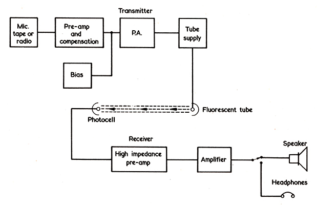
Fig. 8. Block diagram representing the complete installation.
The block diagram of Fig. 8 shows the complete Photophone installation. In this diagram, the pre-amplifier of Fig. 6 precedes the transmitter power amplifier, this coupling into the tube power supply and, thence, to the transmitting fluorescent tube. At the receiving end, the modulated light is picked up by a photocell, the resultant signal being passed to a pre-amplifier, a main amplifier, and a speaker or headphones. An overall compensated response curve is given in Fig. 7.
|