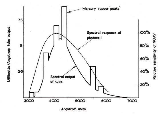
A Wide-Band Photophone

D Bollen The Radio Constructor, January, March & May, 1967.
 

Installation of the Transmitter

Careful screening is necessary at the transmitter end if AC bias is to be employed, otherwise interference will be caused to nearby long and medium wave receivers. The reflector and tube can be mounted on a pole, or placed in a window, where line of sight transmission of several hundred yards can be arranged.

Switch on the power amplifier and tube power supply, and either dab a finger on the open circuit power amplifier input or feed a high level signal to the tube. This should cause the tube to fire and the 100mA meter to read. If all is well, a loud hiss should be audible from the receiver, with possibly a low note of around 700 Hz generated by the tube. With gain set at zero, switch on the pre-amplifier and bias, and adjust VC1 of Fig. 6 (in part one) until the noise at the receiver diminishes. If there is any instability in the system, the back-ground mush will continue or get louder.

When these arrangements are complete a signal can be transmitted and range tests begun. At full modulation the needle of the 100mA meter will begin to flicker and, at the point where excessive modulation is applied, the reading will rise appreciably. At distances up to 100 yards very simple receivers will serve for tests. A selenium cell coupled to a three-transistor audio amplifier allows intelligible short range working, but the frequency response will be poor. Such an arrangement, however, may be used as a field strength meter, prior to more sophisticated reception arrangements. A phototransistor type of receiver will give full frequency response, but tends to be noisy in operation.

For comparison, a 15 watt 240 Volt bulb was connected in place of the fluorescent tube, under similar conditions with the exception that the dropper resistor R1 of Fig. 2 (published last month) was short-circuited so that the lamp glowed brightly. With a wide-band phototransistor receiver, full treble boost and maximum bass cut from a QUAD pre-amplifier (added to the large degree of treble boost given in the Photophone’s compensation network), and taking 200 Hz as the 0db reference point, the signal was down to -10db at 5 kHz, and -15db at 15 kHz. At 15 kHz the bulb was grossly overloaded and threatened to burn out, and this was the highest level of treble pre-emphasis that could be reasonably applied. Under the same circumstances, the fluorescent tube will peak above 30 kHz and maintain its output to well beyond 60 kHz. Without a lens to focus its light to a beam, range from the 15 Watt bulb was inferior, being scarcely 100 yards.

Overall Efficiency

The limit to range with any system employing modulated light is set by receiver noise, light excursion or degree of modulation of the transmitter lamp, and the matching of the lamp’s peak spectral response to the optimum spectral response of the receiving photocell, photodiode, or phototransistor.

With a good design of receiver, the presence of strong ambient light, during the hours of bright sunlight, should have no effect on receiver sensitivity or noise. The resultant effect may be likened to a large DC component upon which a small AC signal is imposed, daylight being the DC component. If a vacuum photocell operated at a low voltage is used, this should contribute virtually nothing to the noise generated by its following amplifier. Unfortunately, phototransistors are not quite so good in this respect, and their noise tends to be significantly high. Light excursion is mainly dependant on the type and power of lamp used. Due to its thermal inertia, a filament bulb is very inefficient at anything approaching high frequencies and the more powerful the bulb the worse does this become, thus setting a natural limit to transmitter power. Discharge tubes will permit large modulation powers without loss of treble response but these, too, do not normally respond to very high frequencies because of the ionisation effects of their gas filling. The efficiency of a fluorescent tube in this context is something of at mystery, but the writer attributes it to the ability of its phosphor coating to respond rapidly to changes in the ultra-violet content of the internal discharge. It is this ultra-violet which activates the phosphor and causes it to throw off. visible light. The performance of different types of tube has already been discussed in Part 1 of this series.

The light output from filament bulbs peakstowards the infra-red end of the spectrum, and phototransistors and caesium oxidised silver photocells are sensitive to this. The fluorescent tube’s maximum output lies towards the blue and ultra violet and, depending on the phosphor employed, a caesium antimony cell will provide a good spectral match. The light output from a fluorescent tube is rather peculiar, consisting of sharp peaks of varying heights and widths distributed along the spectrum. With a caesium antimony photocell, the most efficient tubes to use for an optimum match are Ultra Violet, Blue, and Daylight coatings, in that order. The Ultra Violet tube will be approximately four times as efficient as the Daylight tube. In fact, performance figures given here for the Photophone were based upon Warm White tubes, which are even a less efficient match than the Daylight, so there is considerable scope for improvement. Fig. 9 shows the spectral responses of a Blue tube and a caesium antimony photocell.

Fig. 9. The spectral output of a Blue fluorescent tube and the relative sensitivity of the 90AV caesium antimony photocell. The 90AV photocell is employed in the receiver described in this article.

With the prototype Photophone transmitter at full drive, distortion on peaks was objectionable, particularly when a music signal was being transmitted, and it was difficult to strike a suitable balance between distortion and long range with a good signal-to-noise ratio. Eventually, the simple volume compressor of Fig. 10 was added to the Photophone power amplifier, and this proved to be most effective.

Fig. 10. The simple volume compression circuit employed at the transmitter to obviate over-modulation.

A 6V 0.06A bulb is encased in a small light-tight container, in close contact with. a light dependent resistor type ORP60. As the amplifier output approaches the point where the fluorescent tube overloads and clips the peaks the bulb tends to glow brightly, and its light causes the resistance of the LDR to drop and shunt the PA input, which in turn reduces PA output. VR1 controls the extent to which compression is applied and S1 allows compression to be completely removed when desired. With compression, a very high modulation level can be maintained, to enhance signal noise ratio and increase talk power without distortion.

Range Tests

For range tests with the original, distances were determined by taking a 6 inch to 1 mile map of the area, marking it with 100 yard circles centred on the transmitter location, and identifying the position of the receiver by means of landmarks. The quality of music signals up to 200 yards was excellent, but beyond that the noise level of the receiver tended to drown the quiet passages unless treble cut was used to diminish receiver hiss. At 400 yards speech signals were completely intelligible and the vocal character of the talker came over well. 500 yards seems to represent a light barrier to all moderate power light signals. A tone could just be heard at that distance, using a single 20 Watt fluorescent tube at the transmitter, but speech was indistinct.

The Receiver Equipment

We next turn to the equipment fitted at the receiver end. As has already been mentioned, the performance of a modulated light receiver will be dependent on self-generated noise, ambient light, and correct matching of the transmitter spectral output to the receiver’s photosensitive device. There is also a further factor, this being the optical coupling between transmitter and receiver. Phototransistors were ruled out for the author’s receiver because they are noisy and do not provide a good spectral match to a fluorescent tube. On the other hand, a caesium antimony photocell can be operated at a low voltage to give a good match and adequate gain, with suitable transistor circuitry, as well as a very low noise performance.

The author’s receiver was constructed in two units, these consisting of a photocell pre-amplifier, and a portable audio amplifier with tone controls. The former unit is suitable for feeding directly into a fixed-location valve or transistor amplifier. The portable amplifier was designed to give a good quality output to a pair of Hi-Fi headphones. Alternatively, it can feed into a small 25 to 30Ω speaker at around 400 milliwatts.

Photocell Pre-amplifier

Fig. 11. The circuit of the photocell and pre-amplifier unit. It is recommended by the manufacturers of the photocell that the cathode connection should be made to pins 1, 2, 6 and 7 connected together, and the anode connection to pins 3, 4, and 5 connected together. The output connects to the subsequent amplifier via screened cable with the braiding connected to chassis.
Photocell receiver components list.

The circuit of Fig. 11 shows how a 90AV caesium antimony photocell is coupled to a bootstrapped Darlington Pair. This particular circuit offers a very high input impedance and has the advantage that, with TR1 passing a very small collector current, low noise amplification is possible. Capacitor C3 feeds the bootstrap in-phase signal to the bias network end of R3, and the AC signal from the photocell passes, via C1, to the base of TR1. With this arrangement, tests were conducted using higher photocell voltages, up to 48 Volts, but there was no measurable increase in sensitivity and photocell noise became apparent as voltage increased. C1 effectively blocks the large standing current when the photocell is functioning in bright sunlight, but allows the minute AC signal superimposed on the DC to pass freely to the amplifier. R1 was selected to give the best overall performance. TR3 is a straightforward common-emitter amplifier, coupled to the emitter of TR2. At short ranges, the circuit of Fig. 11 gives headphone strength signals, and the overall response of the pre-amplifier is substantially fiat to more than 60 kHz. The photocell itself has an inter-electrode capacitance of only 0.7pF and appears to be able to respond to frequencies well beyond the capabilities of the pre-amplifier. The output from the pre-amplifier is coupled to the following amplifier by means of a length of coaxial cable.

The collimator box coupled by coaxial cable to the portable audio amplifier.
The inside of the receiver collimator box. The photocell is at the rear with the pre-amplifier before it. The battery is fitted to the right-hand wall of the housing, and the on-off switch to the rear wall at top left.
Return to Contents Page or back to Part one or continue to Part three